The bldg format
The data model and its rules: what a plan stores, the conventions every tool follows, how the compiler builds the geometry and what an LLM is asked to write. The JSON Schemas are published at usebldg.com/schemas/; plans are drawn and changed in the editor (Editor guide).
Why
Floor plans come from many places: a scanned or photographed drawing read by a vision-language model, a CAD or IFC file, a LiDAR scan, a design brief turned into a layout by an LLM, or a person in an editor. bldg is one small, strict, semantic representation for all of them, with a deterministic compiler to SVG, GeoJSON, OBJ and an interactive Three.js 3D view.
| producer | how it gets to bldg |
|---|---|
| raster plan (scan, photo, marketing plan) | a VLM or CV model writes the extract task under a strict JSON schema, in the image's pixels or in mm / inches (the request says which); the engine's ingest places it on the image (the level's underlay), adds the typical set's defaults and builds the types; lint repairs it; the editor's AI assistant does all of it from a pasted image (Trace as new plan) |
| design brief | an LLM writes bldg directly; validation errors go back to it |
| a person | the browser editor: drag corners, draw walls, drop doors, export |
When an agent writes absolute coordinates, every corner and every door is a separate guess: corners don't close and doors float off their walls. bldg changes what gets written:
- Types first. Each wall type (
Q240: its kind and layers, whose total is its thickness, load bearing, fire rating), door / window type (M0921: categorydoor, operationsingle_swing, its rough openingrough{w, h} and, as far as they are known, its frame, leaves and threshold) and component type (bed_1800x2000mm: the catalog familybedand its size) is written once, as in common BIM tools; every wall, opening and component names its type instead of repeating its values, andtypealways means that reference, never a classification. - Shared corners. Each corner is written once, in a shared node pool.
- Walls as edges. A wall is a directed edge between two node ids.
- Openings on their wall. A door or window sits on its
hostwall at a distance from one of the wall's end nodes:anchor(start, the default, orend) andpos(along the wall's node line from that node to the near jamb), its type's rough width, plushinge/swing(sidesA/B). A door without a type is the typical single-swing door of the plan's typical set. - One unit, +y up. Every length of a document is in its
metadata.units,mmorin(no_mmsuffixes, no pixel documents). An image is an underlay: a source whosescale(document units per pixel,calibratedorassumed) and transform place its pixels on the plan. - Project north. Plans are stored straight, in project north (BIM convention): walls of an orthogonal building are horizontal and vertical, whatever angle the drawing had. True north is a separate angle, and each underlay keeps its pixels through its image → plan transform.
- Spaces by their ring of walls. A space stores its
bound(a counter-clockwise ring of nodes along walls, virtual walls included) and optionalholes; an editor click or an agent's pointatis resolved to that ring, so the space follows its walls. The compiler places its name label and works out which spaces every door joins, so none of that is written (or guessed) twice.
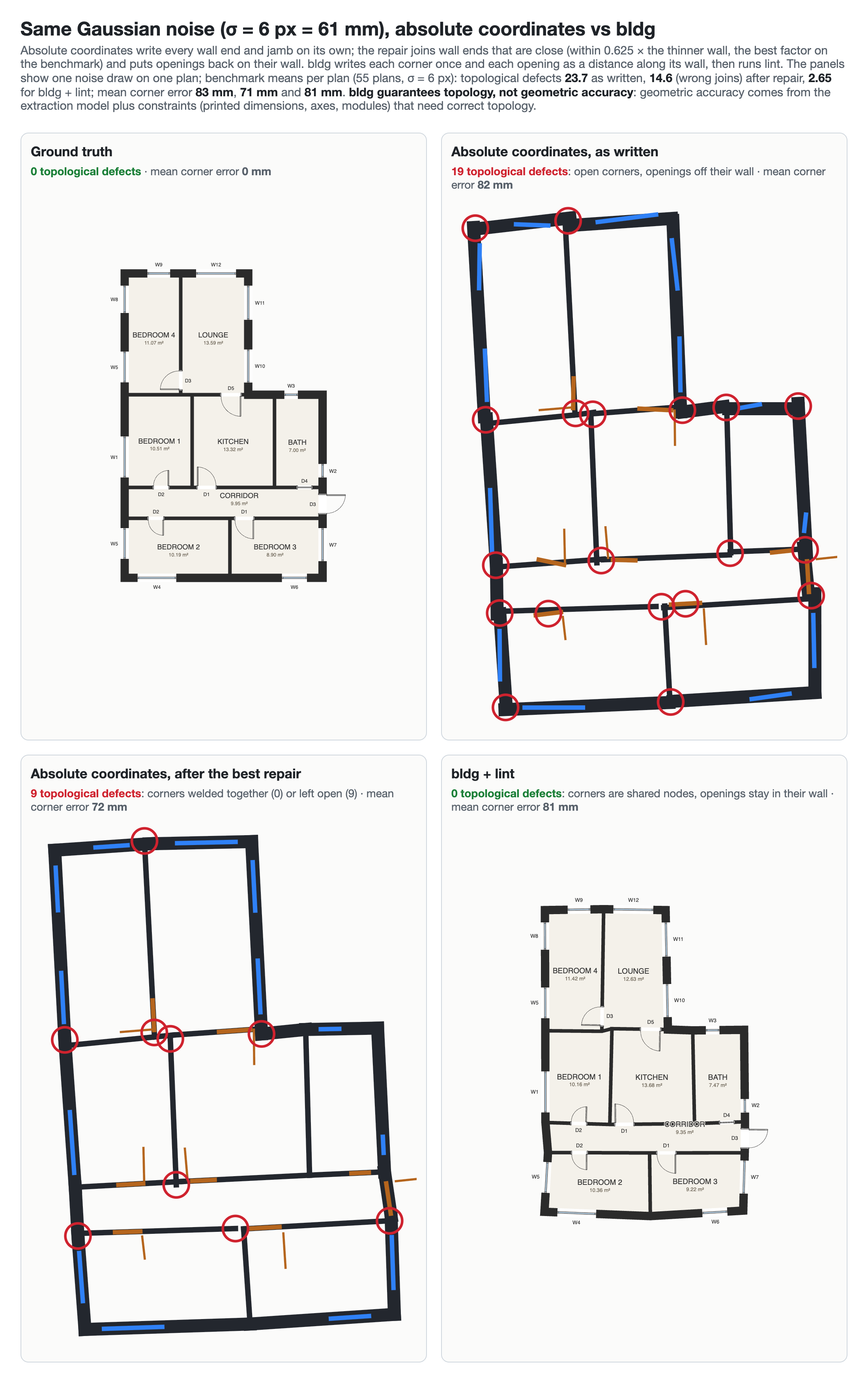
A deterministic compiler does the geometry. Fed the same coordinate noise, bldg keeps the topology: corners stay closed and openings stay in their walls, with nothing to re-join by distance (the best repair of absolute coordinates still joins 14.6 corners per plan wrongly at σ = 6 px). It does not make the coordinates more accurate: the mean corner error is 81 mm, against 83 mm for absolute coordinates as written and 71 mm after the repair, which averages the copies of each corner. bldg guarantees topology, not geometric accuracy; geometric accuracy comes from the extraction model plus constraints (printed dimensions, axes, modules) that need correct topology.
How it differs from existing formats
Each existing format does its own job well: SVG for drawing, DXF for drafting, IFC for full BIM exchange under its formal schema, GeoJSON and IMDF for GIS and venue maps, IndoorGML for navigation. bldg is built for a different job: a plan an AI agent can write under a strict JSON schema, with the building's relations stated once (shared corners, openings hosted on their wall, rooms found from their walls, shared types), and a dedicated edit interface (semantic operations, diagnostics, draft and commit). It is the format you ask the agent for; the others are what you compile to. The sizes below are for one plan with 26 walls, 21 openings and 8 rooms (the dataset's ground truth of synthetic_19, unfurnished: 0 components, not the furnished editor example measured further down), counted with tiktoken o200k_base (plan synthetic_19; the model-side encodings in the image's pixels; SVG and DXF drawn at fine detail; the ratios against bldg's extract answer in the image frame). They are file sizes, each file with its own headers and semantics; the equal-drawing comparison is in Measured benefits. These sizes and the noise figures above come from Measured benefits, measured with the earlier Python implementation of bldg; bldg today writes no DXF or IFC.
| format | walls & thickness | door hinge / swing | shared topology | strict-schema LLM output | same plan |
|---|---|---|---|---|---|
| SVG | shapes only | drawn arcs, no semantics | none | free-form markup | 20.7k (9.0×) |
| DXF | layer convention | blocks + arcs | none | group-code text | 105.3k (45.8×) |
| IFC4 (STEP; ifcJSON not measured) | yes, with types | OperationType LEFT/RIGHT | voids/fills | STEP, GUIDs, placements | 120.8k (52.5×) |
| GeoJSON | polygons | ad-hoc properties | independent polygons | possible, verbose | 23.2k (10.1×) |
| Apple IMDF (OGC Community Standard) | no wall feature | door type, no hinge or swing | openings are separate lines | fixed schema, WGS84 | not measured |
| OSM Simple Indoor Tagging | wall ways, no standard thickness | door=hinged…, no hinge side or swing | shared nodes, doors are nodes on walls | OSM XML/PBF tags | not measured |
| Apple RoomPlan (CapturedRoom) | wall surfaces + 4×4 transforms | door isOpen only | doors/windows → parentIdentifier wall | Codable JSON, 3D matrices | not measured |
| OGC IndoorGML | no | no | cell/transition graph | GML/XML | not measured |
| floorplan/v0 dataset labels | centreline + outline polygon | hinge / tip points | none | one format per dataset | 4.2k (1.8×) |
| raw VLM JSON (absolute coords) | x1,y1,x2,y2 | hinge/tip points | none (23.7 topological defects/plan; 14.6 wrong joins after repair) | ad hoc | 3.1k (1.4×) |
| bldg | yes, layered, by wall type | category + operation by type, hinge + swing per door, exact | shared nodes, openings by distance from a corner (2.65 topological defects/plan) | OpenAI / Claude / Gemini schemas + validators | 2.3k (1×) |
bldg builds on two existing ideas: OSM indoor tagging's shared nodes, and RoomPlan's doors hosted on their wall. It adds wall thickness, exact door chirality and a strict schema a model can fill. Use IFC if you need MEP or a full BIM exchange, IMDF or IndoorGML for venue-scale indoor maps, and SVG if you only need a picture. bldg walls are straight and of constant thickness, so curved or tapered walls must be approximated by segments.
Data model
FloorPlan      { metadata: Metadata, wall_types[], opening_types[], component_types[], rail_types[]^, stair_types[]^,
                 materials[]*, sections[]*, assemblies[]*, finish_types[]*,
                 buildings[], groups[], systems[]*, vertical[], levels: [Level], evidence[]*, external_ids[]* }
Metadata       { schema_version*, units* (mm|in; +y up), true_north?,
                 stage? (concept|schematic|design_development|construction_documents|as_built),
                 jurisdiction? (ISO 3166: US, US-CA, CN-SH; it implies the typical set and the drawing style),
                 codes[] (rule packs with their edition: ibc2027, irc2024, ada2010),
                 typicals?* (bldg:typical_set.international|cn_residential|us_residential; left out: the jurisdiction's),
                 draw?* {style? (bldg:style.international|gb|us; left out: the jurisdiction's)},
                 coverage[]* {collection, where? {kind[], domain[], system_kind[]}, fields[], scope? (a building, level or
                 group; left out: the whole plan), state (complete|partial|not_extracted), tier? (D|R|F)}, document_id?*, defaults*, display_units* (""|mm|cm|m|ft_in|in),
                 display_precision?*, sources[]*, georef?*, catalog[]* }
Source*        { id, format (raster|vector|cad|ifc|point_cloud|text|other|unknown), origin (scanned|manual|generated|
                 dataset|imported|other|unknown), role (plan|brief|reference|other|unknown), uri?, page?, sha256?, license?,
                 note?, dimension_units (mm|cm|m|ft_in|in|unknown), width_px?, height_px?, scale? (document units per
                 pixel), scale_status (calibrated|assumed), rotation, tx, ty (image -> plan transform) }
Georef*        { epsg, eastings, northings, rotation, scale (CRS units per document unit) }
WallType       { id (= the mark: Q240; WT4.5 on US plans), kind (solid|partition|curtain|glazed|virtual|line|marking ...),
                 layers: [{fn (core|structure|finish|insulation ...), t, mat* (a material: bldg:material.gypsum_board),
                 frame*}] (face A to face B; their total is the thickness; a sketch: [{fn: core, t}]; none for virtual),
                 load_bearing? (true|false), fire?* [{min, side, crit, std}], reaction*, acoustic*, u*, key* }
Material*      { id, class (concrete|timber|gypsum|masonry ...), name, density, thermal, draw {cut_hatch} ... }
Assembly*      { id, listing (UL U305), parts {wall}, basis (listed|prescriptive|tested), fire [{min, side}] }
OpeningType    { id (= the mark: M0921, C1515, DK1021; D3068, W4040, CO3068 on US plans), category (door|window|opening),
                 operation? (unknown when left out; an opening has none), rough: {w (the hole in the wall, frame included),
                 h (head - sill)}, sill?^ (default sill), frame?* {jamb, head, sill, stop: [hinge side, latch side], depth,
                 align (A|B|center), offset}, leaves[]* {w, h, t, op, active, sash}, layout?* {split (v|h), at[]}, hinge_gap?*,
                 max_open?* (degrees), clear?* {w, h, area, basis} (left out: derived from the parts), threshold?* {h, depth}, glazed?* (a door's leaves: glass in a frame; left out: solid), fire?* [{min, crit, std}], operation_label*, key* }
ComponentType  { id (bed_1800x2000mm), model (a catalog family, a plugin item or generic), width, depth (the body),
                 height^ (0 = the family default), params[] ({name, value}), category ("" = the family's; generic only), name*, key* }
Building       { id, role? (project|context), name?, number*, addresses[]*, class? {ibc_const (IA … VB)},
                 podium_of? (a building), at_grade? [level id ...] (left out: its lowest storey) }
System*        { id, kind (sprinkler|standpipe|fire_alarm|voice|... ), std? (a sprinkler's: nfpa13|nfpa13r|nfpa13d|gb50084),
                 covers [building, level, space or group id ...], excludes [id ...] }
Group          { id, kind (dwelling_unit|sleeping_unit|occupancy|fire_area|fire_compartment|tenancy|common_area|
                 open_plan|other ...), name?, parent? (a group or building), members: [{ref (a record of any level),
                 role?}], class? {ibc_occ (A-1 … U)}, unit? {access? {a117 (type_a|type_b|type_c|accessible|none),
                 ada (accessible|none)}, entrance: [opening id ...], template?} (dwelling and sleeping units only) }
Level          { id, name, building? (left out: the only project building), elevation^ (the datum: the top of the
                 structural slab), floor?^ (the finish build-up above the datum; left out: the typical set's),
                 ceiling?^ {id, z} (the ceiling above the datum its spaces inherit; left out: none), height?^,
                 slab_thickness?^, wall_angles[], underlay* (a raster source id),
                 nodes[], walls[], spaces[], openings[], components[], rails[], dimensions[], grid[], texts[] }
Node           { id, x, y }
Wall           { id, start, end, type (a wall type, or a library one: bldg:wall_type.virtual), fn?* [party|fire_barrier|parapet ...],
                 flip?*, base?*, top?* | top_to?* [ceiling ids] + top_over?* (left out: up to the slab or storey above),
                 assembly?*, stack?* [{z: [z0, z1], type}], finishes?* }
Space          { id, name? (the label), use? (left out: unknown, inferred from the name and components),
                 habitability? (habitable|occupiable|unoccupied), sleeping? (left out: from the use), class? {ibc_fn (the
                 IBC Table 1004.4 function: business, residential ...; left out: from the use)}, egress? (exit_access|exit|
                 exit_stair|exit_passageway|exit_discharge|refuge), load? {posted, seats, bench}, bound: [node id ...] (counter-clockwise,
                 each pair joined by a wall), holes?: [[node id ...] ...] (clockwise), within? (the parent space),
                 kind? (interior|exterior|plenum|lot), semi? {kind (balcony|loggia|terrace|porch|arcade|carport)},
                 number*, floor?^: [Patch] (exceptions to the level's floor: a raised floor, a ramp's slope),
                 ceiling?^: [Patch & {form? (main|furred|dropped|sloped)}] (exceptions to the level's; z required),
                 label_offset*: [dx, dy] | [] }
Patch          { id, ring? ([[x, y] ...]; left out: the rest of the space), z (above the datum at at), at? (required with
                 slope), slope? {dir: [dx, dy] (integers), rise, run} }
Vertical       { id, kind (stair|ramp|shaft), name?, stops: [{level, at (an opening, space, flight or landing there)}],
                 stair: type? (a stair_types id | bldg:stair_type.typical), form? (straight|two_flight|switchback|l_landing|
                 l_winder|u_winder|scissor|spiral|curved), enclosure? (a shaft), enclosure_kind?, flights: [Flight],
                 landings[]? {id, level, ring, z}; ramp: use? (pedestrian|vehicular), runs: [{space, dir}], edge?;
                 shaft: members: [{ref (a space)}] }
Flight         { id, level, base: [[x, y], [x, y]] (the bottom nosing line, left to right looking up), dir, z: [z0, z1]
                 (above the level's datum), risers, goings: [going] (one: every tread), steps[]? (winders), outline?,
                 type? }
Rail           { id, type (a rail_types id | bldg:rail_type.typical.guard|handrail), path: [[x, y] ...] | along: [wall id
                 ...] (a chain of walls), z[]? (the top at each point; left out: the walking surface + the type's
                 height), of? (the flight, ramp run, landing or space it serves), side? (left|right, looking up) }
RailType^      { id, kind (handrail|guard|grab_bar|wheel_guide|vehicle_barrier), height?, clear? {sphere, triangle, basis} }
StairType^     { id, structure, open_risers?, landing? }
Opening        { id, type? (left out: the typical set's typical door), host (a wall), anchor (start|end; start when left out),
                 pos, hinge? (start|end), swing? (A|B|both), egress? (A|B), roles? [egress|exit|exit_discharge|eero ...]
                 (left out: none declared; an at-grade level without exits counts its exterior doors), sill?^,
                 clear?* {w, h, area, basis}, mark* }
Component      { id, type, x, y, dir? ([dx, dy]: the type's local +x, two integers in lowest terms, each at most
                 1000 in size; [1, 0] when left out), mirrored* }
Dimension      { id, x0, y0, x1, y1, text ("" = drawn: measured live and shown in the display units; otherwise as printed
                 = evidence), basis (centerline|face|overall|unknown), offset* (the dimension line's signed distance
                 from the points, + = visual left of p0 -> p1; 0 = on the points; extension lines join them),
                 host0*, host1* (what each end is attached to) }
GridLine       { id, label, x0, y0, x1, y1, bubbles* (both|start|end|none: the ends that show the bubble) }
Text           { id, role (room_number|area|mark|level|note|other), ref ("" = none), text, x, y }
Evidence*      { ref, aspect, method (measured|drawing|traced|read|inferred|assumed), source, needs_check, note? }
ExternalId*    { ref, source, external_id, role (element|void|fill|type) }
(wall kinds: solid|partition|curtain|glazed|demountable|operable|toilet_partition|frame|virtual|line|marking|curb|fence; load_bearing: true|false, left out = unknown; opening operations: door single_swing|double_leaf_swing|sliding|pocket|bifold|folding|overhead|revolving|pivot, window fixed|casement|sliding|hung|awning|hopper|tilt_turn|pivot|removable|folding, both unknown|other, opening none; space uses: living|bedroom|kitchen|dining|bathroom|half_bath|laundry|closet|corridor|entry|garage|storage|utility|office|stair|other)
The rules:
| R1 | type always means a reference to a type definition; it never classifies. |
| R2 | Every repeating element has a plan-wide type table: wall_types, opening_types, component_types. |
| R3 | A classification, size or construction lives on the type (or the catalog family), never on the instance. A per-instance change retargets the instance to a reused or new type in the same transaction. |
| R4 | Classification words: opening type category + operation; wall type kind; text role; space use; group kind; source format / origin / role; component type model (its category from the family). A space's kind (interior | exterior | plenum | lot) says what sort of area it is. |
| R5 | Every length of a document is in metadata.units, with no _mm suffix; both units are +y up. Pixels exist only on a Source (the underlay) and in the LLM image frame. |
| R6 | Units are never guessed from field names: every interface states its frame and length unit, and conversion runs through one field-dimension registry. |
| R7 | A component type's model is a catalog family id (or a plugin item id, or generic), never a sized or preset id. |
Naming rules: start / end are a wall's end nodes, 0 / 1 a dimension's or grid line's ends; angles are degrees counter-clockwise, with no _deg suffix; an argument that takes a wall position is on; booleans are bare adjectives (sleeping, external, mirrored); identifiers use US spelling (centerline, neighbor_openings); ref is always an element id.
* marks document-only fields and ^ DETAIL fields (heights a drawing rarely prints: the extract task leaves them to the plan's typical set). Fields are in generation order: what an element refers to comes first (the types, then per level nodes, walls, spaces, then openings and components; an opening's type, host and anchor before its distances). Sentinels free the strict-schema union budget and say what they mean: none = does not apply (a window's hinge), unknown = applies but not visible (a hidden swing); "" = no text reference, the family's category.
A space stores its ring of walls: bound, its outer ring of node ids counter-clockwise, each pair of consecutive nodes joined by a wall of the level (a virtual wall for an open side), and holes, the clockwise rings of the wall islands inside it, so the space follows its walls when they move. A point at inside a ring is how the editor's Room tool, the add_space op and a model's trace name a space: it is resolved to the ring of walls around it and never stored (a file written with at and no bound is read with it resolved, and lint writes the ring). within names a parent space (a stall in a toilet, an alcove); spaces on one level, or within one space, never share a ring side or overlap. The name is drawn at an automatic spot inside the space, clear of furniture and door swings (label_offset moves it; the editor writes it when a label is dragged). The spaces on both sides of an opening always come from the geometry (OpeningGeom.spaces), and that is what the space graph, the schedule and GeoJSON use.
* marks document-only fields: tools fill them (provenance, including the underlay's pixel size, scale and transform; a stable document id; georeferencing; embedded plugin models; door / window assemblies; evidence and external ids; area overrides). The LLM schemas leave them out, so a model never pays tokens for them. A space is one bounded area (BIM's IfcSpace): a room, a terrace, a lot; a balcony, loggia or porch is a space with semi.kind. A group gathers records of any level (IfcZone / IfcGroup): the rooms of one dwelling unit, an occupancy, a fire area, an open-plan area made of several rooms; a space may be in several groups. The clear height of a space is derived, never stored: its ceiling (its own patch, else its level's) less the finished floor (the level's datum plus its floor build-up); with no ceiling, the soffit of the level above less the floor bounds it. Sills are measured from the finished floor. A missing stage, jurisdiction, code, use, floor or ceiling never makes a plan invalid: it is not declared, and the typical set stands in where a value is needed. A virtual wall is a room separation line (open-plan kitchen / living): it closes rooms but has no body and hosts no openings. unknown hinge or swing means the operation is visible but its direction is not, which is different from none (the operation has none). coverage (document-only: the caller of ingest passes it, default unknown) says which layers were not extracted, so an empty list is not mistaken for "none". Full field reference: the storage schema, FloorPlan.schema.json (JSON Schemas).
Types first (the BIM type / instance model). Every wall has a wall type, every door / window / opening an opening type and every component a component type, plan-wide (every storey shares them) and written before the levels. An agent writes {"id": "WT1", "kind": "solid", "layers": [{"fn": "core", "t": 240}]} once and then {"id": "w1", "start": "n1", "end": "n2", "type": "WT1"} per wall, not the kind and thickness on every wall. A type's id is its mark, in the plan's drawing style (see Typical sets): international marks are sequential per category (walls WT1, doors D1, windows W1, openings O1; SEP for a room separation line) and never change on a resize; China (cn_residential) uses GB size marks: walls Q + thickness in mm, doors M0921 (900 x 2100), windows C1515, openings DK; the United States (us_residential) US marks: walls WT + nominal inches (WT4.5), doors D3068 (3'-0" x 6'-8"), windows W4040, openings CO3068; component types <family>[_<option>]_<W>x<D>mm (_in on US plans). A taken size mark gets a letter (Q150a: same thickness, another kind, load-bearing or layers); on China / US plans types whose size was traced on an assumed scale are numbered (Q1, M1, bed1) and get their size marks from the first calibration (set_scale with adjust: traced); a size an edit op is given as a number (a palette preset, a typed width) or takes from the typical set / catalog is a spec, not a tracing: it gets an assumed evidence record, and the Scale keeps it. A size mark follows a size edit (edit_type, re-marked with every reference); a sequential or hand-named id never changes, and neither does any id on set_units or a change of jurisdiction or drawing style. An opening's head is its sill (its own, else the type's default, else the typical set's) + the type's height, so one window type sits at several sill heights; hinge, swing, position and tag stay on each opening. An instance never overrides its type: an edit that changes one door's width, one wall's thickness or one bed's size moves that element to a reused or new type. resolve_types gives a read-only inline view (every instance with its type's values) for tools that work on raw JSON. Validation names a missing or wrong type (type 'M0921' is an opening type, not a wall type); the checks list unused types; factor_types types a plan written inline. The marks are printed beside each door and window in the drawing, and the door / window schedule (the editor's Schedule tab) has one row per type: mark, size, count, rooms. On the demo plan the 26 walls share 2 wall types, the 21 openings 14 opening types (its traced windows have 14 sizes) and the 30 components 21 component types; the extract answer (plan frame, mm, minified) takes 4,282 tokens (o200k_base). The types pay off where sizes repeat, less on a plan with traced sizes like this one.
Units and canonical form. metadata.units (mm or in) is the unit of every length in the document: coordinates, wall thickness, opening pos and width, heights, sills, elevations, construction sizes, component sizes and length parameters, metadata.defaults. Both are +y up. The display units (metadata.display_units, else the document unit's own: ft-in on an inch plan) change only what people read and type, never what is stored; the editor's Settings ▸ Units & standards picks both together (below). Canonical form keeps mm to 2 decimals and inches to 4 (0.0001 in = 0.00254 mm; the display default is 1/16", and 1/256" still shows back as typed), angles to 0.1°, and the image transforms (scale, rotation, tx, ty) and Georef.scale to 12 significant digits. Values are computed in double and quantised once, at serialisation or op commit. Rounding is half away from zero, the same rule as the displayed values (the editor's length display rounds the same way), and integral values are written as integers (900, not 900.0). Validation accepts any precision; the canonical form (canonical_dict / canonical_json) rounds, leaves out every field equal to its default (and every component type parameter equal to what the family derives) and puts one node, wall or opening per line, and every tool that writes a plan writes this form. Rounding keeps a plan valid: openings keep their jambs on the rounded walls and move inwards when the nearest step would touch a junction. set_units (the op, the editor's Settings ▸ Units & standards across mm / inches) converts every length once from the stored values through the field registry: mm → in → mm is exact on the 0.01 mm grid, in → mm → in moves a value by at most 0.00508 mm; ids, references, the jurisdiction, typical set and drawing style, the display units and the catalog definitions (always mm) stay. On the demo plan (editor/examples/synthetic_19.bldg.json: 26 walls, 21 openings, 8 rooms, 30 components, 8 printed dimensions; tiktoken o200k_base) the canonical file takes 6,075 tokens (4,557 minified).
Every collection is an array of objects identified by id. No schema uses dynamic keys. Every object is closed (additionalProperties: false) in the canonical, OpenAI and Claude schemas; Gemini's response_schema cannot express that, so decoded output is always validated again against the full model. IDs are unique across the whole plan, the three type tables and the sources included.
Typical sets, drawing styles, defaults and units
Most values in a plan are conventions nobody draws: the storey height, the slab, the door head, the window sill, the railing height, door leaf and frame sizes, the stair tread depth. A model should not have to generate them, and a tool should not pass a preset off as a measured fact. metadata.jurisdiction (an ISO 3166 code) says where the building is, and it implies two things: the typical set, the values that fill in what the drawing leaves out (default heights, furniture presets and checks, size sets, the typical door), and the drawing style, how the plan writes its type marks and grid letters. The jurisdictions table looks up the code, then its country (US-CA as US): US gives bldg:typical_set.us_residential, the bldg:style.us marks and inches for a new plan; CN gives bldg:typical_set.cn_residential and bldg:style.gb; any other code, or none, gives bldg:typical_set.international and bldg:style.international, in mm. A sketch needs none of it. The optional metadata.typicals and metadata.draw.style (document-only) pick another set or style; metadata.defaults overrides single default values; and one resolver returns every value with its origin: explicit, type, catalog, typical or inferred. The GB/T 50353 area estimate follows the jurisdiction (in China), whatever the typical set.
| none or another code: international | CN: cn_residential, gb | US: us_residential, us | |
|---|---|---|---|
| type marks (style) | sequential: D1, W1, O1, WT1 | GB size codes: M0921, C1515, DK1021, Q240 | D3068, W4040, CO3068, WT4.5 |
| areas | gross floor area + room net areas | + building area estimate (GB/T 50353) | gross floor area + room net areas |
| furniture checks | the family's range only | + the 50 mm module | + the 1/2" module |
| storey height / slab | 2800 / 150 | 2800 / 120 | 8'-0" / 12 5/8" |
| door head | 2100 | 2100 | 6'-8" (2032) |
| window sill / head | 900 / 2100 | 900 / 2400 | 3'-0" / 7'-0" |
| railing | 1100 | 1100 | 3'-0" |
| stair tread depth / max riser height | 260 / 180 | 260 / 175 | 10" / 7 3/4" |
| wall thickness set (lint) | 100 115 120 125 175 180 200 240 300 365 370 | 100 120 180 200 240 370 | 4 1/2" 5 1/2" 6 1/2" 8" |
| door widths (lint) | 625 .. 1125 | 700 .. 1000 | 2'-4" .. 3'-0" |
| a new plan stores | mm | mm | inches (shown in ft-in, 1/16") |
Type marks. A type's id is its mark (no separate mark field). International marks are sequential per category (doors D1, D2 ..., windows W1 ..., cased openings O1 ..., walls WT1 ...; room separation lines SEP): they do not encode a size, so resizing a type never renames it. China and US marks encode the size and follow a resize (M0921 -> M1021, D3068 -> D3268), as those conventions expect. Component types keep their readable <family>_<size> ids (bed_1800x2000mm, US bed_60x80in). Changing the drawing style (or the jurisdiction that implies it) never renames existing types; new types follow the new style. Nothing keys on a mark: a type's identity comes from a stable key (type_keys: the first element that uses the type, written once as the type's internal key when an edit would change that element), so renames, resizes and adding or deleting doors keep it. A China / US size mark names a height, so a door or window type the editor makes under one (M1021, D2868) stores the height its mark names; sequential types follow the typical set's door head / sill.
Areas. Every plan shows the same plain geometry (floor_areas / plan_areas): Gross floor area to the modelled outer wall faces (stairs, shafts and unroomed spaces included; open courts, balconies and terraces not; no height rules, no half counting), Room net area per room (inside the wall faces) and the Total room net area; balconies and terraces are listed apart at their full net area. Plans in China (jurisdiction CN or a subdivision) add a building area estimate, the GB/T 50353-2013 rules (storey_area / building_area: low storeys and balconies outside the main structure count half, 套内 areas per unit), with the method and its unverified status in the report; Other plans never run the GB rules. With several storeys the editor's Areas tab ends with the building's totals (all levels).
Storeys stack. A level on top of the one below (elevation = its elevation + storey height, as add_level places it) follows a storey height change: set_level height and the editor's Settings (storey height, jurisdiction, typical set) move the storeys above in the same step (restack_levels). A level set apart by hand stays, and the Problems panel names the gap or overlap (level_stack_mismatch, a warning).
Furniture. Catalog sizes are free within each family's range; the typical sets' sizes (US mattresses, GB beds) are presets, never a warning. The China and US sets also check lengths against their module (50 mm, 1/2").
Sources: GB 50096 and GB/T 50002 / 5824 (cn), IRC 2021 and US stock sizes (us). Values a plan leaves unknown are inferred, never stored: whether a solid wall is exterior or interior is inferred (exterior on the outer outline of the walls, else interior; ext~ / int~ in the read view); an unknown room use comes from the name (the keywords of every bundled language, merged), else from the families of the components inside (room_use_inferred). The checks print the typical set and one [assumed] / [inferred] summary line per property (storey height: 2800 mm x1 (bldg:typical_set.international), door head: 2100 mm x8); the schedule marks typical heights as assumed; validation errors name the origins (sill 2200 mm (explicit) must be below head 2100 mm (typical)).
Units. A document is in mm or in inches (metadata.units; a new document takes its jurisdiction's: in for US, else mm; a jurisdiction never changes the unit of an existing one), and every length in it is in that unit, with no suffix. Typical-set values and catalog definitions are internal mm tables; metadata.defaults overrides are in the document unit. A model is asked in an explicit frame and unit, never guessed: the schema of a task names its frame (plan or image), its length unit (mm or in) and, in the image frame, its coordinates (px or norm1000). In the plan frame every coordinate and length is in length_unit, +y up; in the image frame coordinates and planar lengths (thickness, rough width, pos, a component's size) are pixels of the level's underlay, x right, y down from its top-left corner (or 0..1000 of its width and height with norm1000, the Gemini convention), and heights are in length_unit. Each numeric field's description says its unit, built from the field-dimension registry. ingest maps the answer once, in double, and quantises it at the end; values outside the image are clamped with a warning (nodes_clamped_to_image). The same plan written in mm, in inches or in the image's pixels ingests to the same document; the strict-union count is the same in every frame and unit. What people type and read is a separate, document-only choice: metadata.display_units (mm, cm, m, ft_in, in; default the document unit's own: ft_in on an inch plan, else mm) and display_precision (1/2" .. 1/256", default 1/16"). The editor has one unit for the whole plan: Settings ▸ Units & standards offers mm, cm, m, ft-in and in (and, for ft-in / in only, the imperial precision). mm / cm / m keep the plan in mm and ft-in / in keep it in inches, so a choice within a family only changes the display, and a choice across them converts the plan once with set_units, without a confirm, as one undo step (the toast says Converted from mm to inches). The choice is saved in metadata.display_units / display_precision, so Save, a share link and a reload open the plan the same way. The jurisdiction, typical set and drawing style stay, so a plan without a jurisdiction or a China plan switched to ft-in keeps its marks (US marks come only with the bldg:style.us style). The read-only viewer (?mode=view, ?embed=1) has no Settings: it shows the plan in its saved display unit. parse_length reads metric with suffixes, the feet-and-inches forms of common BIM/CAD practice (12'6", 12' 6 1/2", 12'-6", 6 1/2", and 12-6 / 12 6 when the unit is ft-in), thousands separators and decimal commas, and = expressions (=1200+2*600, =12'6" - 4") with a safe recursive-descent parser, into the document unit; format_length writes 1200, 120 cm, 1.20 m, 2' - 6 1/2". The editor's length fields use it, and give the same results on the same cases. Printed dimensions are read with Source.dimension_units, so an unsuffixed 4.60 is not taken for metres when the sheet is in cm.
Normative conventions
Project north and true north. As in common BIM tools, geometry is stored in project north: up on the plan is the building's own up, and the walls of an orthogonal building are horizontal and vertical (wall_angles [0], plus a genuine second axis such as a 45° wing). straighten puts a plan there: it turns the whole plan about the centre of its nodes by the smallest angle that brings the dominant wall direction to 0 / 90°, then removes skew under 0.5° (walls that close to the axes are made exact), and turns everything that has a position or a direction with it. ingest, lint (when asked to straighten) and the data builders all call it, so a model may write the coordinates of a drawing that is a few degrees off as they are on the image. True north is metadata.true_north, an angle in degrees counter-clockwise from project north (a north arrow read on the image turns with the plan); the SVG draws a north arrow, and the editor can turn its view to it (the data stay in project north).
Units and underlays. metadata.units (mm | in) is the only unit of the geometry; both are +y up, and the origin is arbitrary (georef places it in a projected CRS: Georef.scale is CRS units per document unit, 0.001 for mm to metres, 0.0254 for inches). An image is not a frame but an underlay: a Source of format raster with width_px / height_px, a scale (document units per image pixel; null = not registered) with its scale_status (calibrated, measured against known lengths, or assumed, a stand-in: an uncalibrated traced plan is still mm or in, with the stand-in 10 mm/px converted to the unit) and the transform rotation, tx, ty. Each level names its image (Level.underlay; "" = the first raster source with a scale), so levels can be traced on different images at different scales, all in one document unit. A pixel (u, v) of the image (origin its top-left corner, v down) lies at
plan = (tx, ty) + scale * R(rotation) * (u, -v) (source_matrix / source_to_plan / plan_to_source)The editor draws the image through it, so a straightened plan still lies on its drawing. The editor's Scale tool (the set_scale op) registers or corrects it: adjust: underlay only re-registers the image (nothing in the model moves); adjust: traced corrects a traced scale, mapping every coordinate and planar length traced on that image (and type sizes without evidence or with traced evidence) through the old and the new transform, while independent specs keep their values (every height and sill, type sizes that were read, measured or assumed) and are listed (scale_kept_specs). ref, hinge, swing and rotation are the same in every unit.
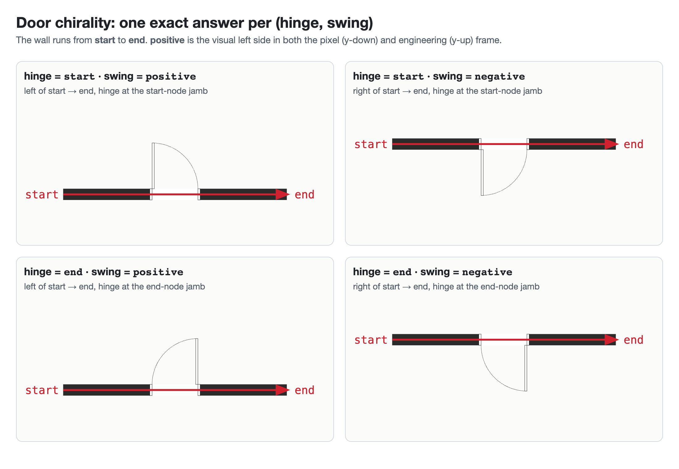
Chirality. Take a wall with unit direction d = (end - start)/|end - start|. In the plan (+y up) n_A = (-d.y, d.x); in a y-down view (SVG, the LLM image frame) it is (d.y, -d.x). Side A is the left-hand side of someone walking from start to end on the plan as drawn, B the right, and this holds in both frames.
Openings. R(n) is the setback at wall end n: the distance along the centreline from the node to the face of the wall met there (half its thickness at a 90° corner, T or X; at an obtuse corner the far point of the slanted junction cut, (h_K + h_H |cos a|) / sin a, so an opening whose return there is 0 is never clipped by the junction; 0 at a free end; walls within 15° of its line, continuations and overlaps, are skipped). With L the wall length, the opening covers, measured from start:
anchor = start:   s0 = pos             s1 = s0 + width
anchor = end:     s1 = L - pos         s0 = s1 - width
Its returns, the solid wall between each jamb and the face of the wall met at that end, are s0 - R(start) and L - R(end) - s1. The rough span must lie on the solid part of the wall, between R(start) and L - R(end) (T7): an opening of a type that reaches past it is invalid; a typical door (no type, its size a premise) that does so gets an opening_off_host warning and is clipped where it is drawn. Tools measure from the end with the smaller return (a tie goes to start).
hinge: startplaces the hinge at the jamb towards the wall'sstart.swingis the side the leaf opens into.- The leaf hangs on the swing-side face of the wall.
- When open, the leaf has rotated 90 degrees and points along the swing normal.
The rotation sense is recorded per leaf (turn), so the SVG sweep-flag, computed in the SVG's own Y-down frame, follows without ambiguity.
Benchmark check: d_wc on w_mid (n4 to n3, pointing +x, 1725 mm long) has anchor=start (left out), pos=132.5 and, from its type D1, a rough width of 700. w_left (125 mm) meets n4, so R(n4) = 62.5, its return there is 70 and the door covers 132.5 to 832.5 mm from n4. With hinge=start and swing=B it opens towards -y, into the WC; its leaf is hinged at (7632.5, -5350) on the WC face. In the SVG (y down) that gives A 620 620 0 0 0; at medium detail the arc is centred on the hinge at the inner face of the 40 mm frame, (7672.5, -5350), radius 620 (700 minus both frames).
One exact answer for every door
Side A is always the visual left of start → end as the plan is drawn (both document units are +y up; in the LLM image frame, y down, it is the same visual left). hinge = start | end picks the jamb. The drawn arc (the SVG sweep-flag) and the 3D leaf are both derived from those two fields.
Where a door sits. The stored position is pos, along the wall's node line from its anchor node to the near jamb, in the document unit: it needs only the node coordinates, not the setbacks. Architects dimension a door by its return, the solid wall between the jamb and the face of the wall it meets (e.g. 120 mm): that is pos - R(anchor), derived, and the editor's locked dimension shows and edits it. Because the position is a distance from one node, a door keeps its pos when the far end of the wall moves or a neighbour's thickness changes, follows its node when that node moves, and keeps its pos (its anchor flipped) when the wall is reversed, like a locked dimension in common BIM tools; an op's neighbor_openings: keep_return keeps the return instead. The compiler reports both built returns of every opening (return_start / return_end in SVG, GeoJSON and the check results), and the check advises on nibs under 50 mm. Snapping returns to standard values is opt-in (the linter's snap_returns_mm option, for example 0, 120 and 240 mm).
Compilation (no CSG)
1. Junctions (BIM-style wall joins)
Each node is classified, and CompiledLevel.joins records the result:
| Case | Treatment |
|---|---|
| T or X (a near-straight pair, within 15°) | The pair runs through, cut square on its joint line; every other wall butts square onto its face. With several candidate pairs, priority decides. |
| L corner | Butt (default, BIM convention): the higher-priority wall runs to the outer corner and the other stops on its inner face. The compiler's corner_join: miter option gives 45° corners instead. |
| Corner with extra walls (e.g. a diagonal into a room corner) | The two strongest walls form the L, and the rest butt onto the corner's faces |
| Near-straight continuation or thickness step | Bisector cut |
| Three or more walls with no usable pair (Y), sharp reflex corners | Mitred around the node, or bevelled; the bevel is owned by the arm whose visual left faces the gap, so pixel and mm outputs agree |
| Wall end lying inside another wall's body (an implicit T) | The stem stops flush on that wall's face |
Priority for "who runs through": the role a wall's type kind and layer functions give it (a solid wall, exterior or interior, and a party wall first, then curtain and glazed walls, then partitions, then the rest), then load-bearing (yes, unknown, no), thickness, length, id. A butt join that would not tile cleanly falls back to the mitred solution for that node. Wall bodies never overlap and never leave gaps.
2. 1D Boolean
Each opening's span (from anchor and pos, above) is subtracted from the wall's length, and the remaining spans become wall-segment polygons.
- An opening that reaches into a junction zone is clipped, with a warning.
- A junction cap is always emitted, even when an opening runs up to the node.
3. 3D
The walls are built from separate closed prisms, each with outward normals, and with no Boolean subtraction:
| Piece | Height range |
|---|---|
| Full-height solid segments | [0, H] |
| Headers | [head, H] |
| Window sills | [0, sill] |
| Room slabs, on the centreline polygons | [-slab, 0] |
| Slab bands under every wall half that no room covers | [-slab, 0] |
The pieces touch face to face, so the slab layer tiles rooms plus wall bodies exactly. Net room outlines (inside the wall faces) are computed for areas and labels.
topology_report lists non-fatal input problems: implicit T-junctions, walls that cross or collide without a junction, near-duplicate nodes, walls shorter than their junctions, openings that reach into a junction, and orphan nodes. The compiler assumes none of the warning-level ones are present.
LLM structured outputs
One field definition gives three tasks (llm_schema(dialect, task, frame, length_unit, coords)), so a model is asked only for what the task needs, in a frame and unit the request states:
| task | asks for | decoded by |
|---|---|---|
extract | what a drawing shows: the wall and opening types first, then nodes, walls, spaces (each a point at inside it), openings, components (observations: family model, size and parameters inline), dimensions, grid, texts, metadata.jurisdiction and true_north; no document-only fields (units, sources, scale, coverage, mirroring ...), no DETAIL heights | ingest (in the image frame: placed on the image) |
detail | extract + storey / slab / elevation, wall and type heights, sills and heads, ceiling and component heights | the same |
edit | {"wall_types", "opening_types", "component_types", "delete_types", "edits": [{level, nodes, walls, ..., texts, delete}]}: types and elements by id (every instance of a changed type follows; a new short id such as o3 adds one), ids to delete; the rest stays. Always the plan frame and the document unit | apply_edit(plan, edit) |
Decoding has a fixed order: model output → the stated frame and unit (image pixels through the underlay's transform, or plan lengths in length_unit) → document unit → document context (the image as underlay with its size and scale, the jurisdiction; or the stored plan, whose document fields, DETAIL heights and the types' document fields are kept; a context in another unit is converted first) → component types (equal specs share one, the context's first; sizes of 0 take the typical set's default, recorded as assumed) → project north (straighten: a drawing a few degrees off is turned straight, its north arrow and the image's transform with it) → full validation. Nothing is detected from field names or magnitudes. emit_dict(plan, task, frame, length_unit) is the inverse, what a model should write for a stored plan (few-shot examples in generation order): canonical_dict(ingest(emit_dict(p, t, f, u), p, f, u)) == canonical_dict(p) for detail in either frame and unit (the image frame is written to 0.1 px, so a plan on that grid comes back exactly), and for extract where the stored plan supplies the DETAIL heights it leaves out; emit_dict(p, "edit") is a PlanEdit that rewrites every element and validates against the edit schema in every dialect, and apply_edit(p, emit_dict(p, "edit")) leaves the plan as it is.
| Dialect | Use |
|---|---|
openai | OpenAI Chat Completions / Responses structured output with strict: true. Every property is required and optional ones are nullable. |
anthropic | The input schema of a Claude tool with strict: true. All properties are required (Claude limits strict schemas to 24 optional parameters). Numeric constraints move into descriptions. |
gemini | Gemini response_schema. $ref is inlined and nullable is used. Keywords Gemini does not support are moved into descriptions; propertyOrdering keeps the generation order. |
canonical | Draft 2020-12 JSON Schema; with no task, the storage schema of a whole document (the files below). |
Claude's strict tool use allows 16 union-typed properties over all strict schemas of one request. Sentinels (none / unknown / "" instead of null for hinge, swing, load-bearing, text reference, a generic type's category; 0 for equal door leaves and for a family's default size) and the tasks keep the count at 3 (extract), 9 (detail) and 3 (edit), the same in every frame and unit, so extract + edit (6) and detail + edit (12) each fit in one request. Measured on the demo plan (o200k_base; outputs minified, schemas written with , and : separators):
| extract | detail | edit | |
|---|---|---|---|
| model output, demo plan (26 walls, 21 openings, 30 components; 2 + 14 + 21 types), plan frame mm | 4,282 | 4,694 | 5,230 |
| the same, image frame (px, 0.1 px) | 4,181 | n/a | n/a |
| model output, laundry benchmark (5 walls, 2 openings; 4 + 2 types), plan frame mm | 540 | 594 | 563 |
schema (Claude input_schema) | 4,732 | 5,414 | 5,372 |
| schema (OpenAI) | 4,793 | 5,467 | 5,423 |
| strict unions (Claude) | 3 | 9 | 3 |
The schemas carry the type lists, the component observations and the unit words in every numeric field's description; the edit task writes the plan's component types too. The type ids name the sizes they stand for (bed_1800x2000mm), so they are read once, not per piece.
Constraints that a dialect cannot express are always enforced again by the full validation after decoding. Send the validation errors back to the model for a repair turn. Line breaks and control characters in names are normalised to spaces.
JSON Schemas
The format's JSON Schemas (Draft 2020-12) are published on this site, so any tool can check a file the editor writes:
| schema | what it describes |
|---|---|
FloorPlan.schema.json | a whole plan, *.bldg.json ("schema_version": "bldg/0.2"; a bldg/0.1 file is read and moved to 0.2): the storage schema |
PlanEdit.schema.json | the edit task: types and elements by id, ids to delete |
SpaceObservation.schema.json | a space as a model reads it: a point inside it, its name and use |
ComponentObservation.schema.json | a component as a model reads it: the family, the size and the parameters inline |
Each is served at https://usebldg.com/schemas/<name>.schema.json, with that URL as its $id and the Draft 2020-12 dialect as its $schema. The format is open: anyone may read and write .bldg.json files with their own tools.
Component catalog and plugins
The component catalog is a built-in library of 37 parametric families (beds, wardrobes, desks, sofas, dining sets, the 600 mm kitchen module, sanitary ware, appliances, columns, lifts, escalators, air conditioners, plants, trees and generic) with Chinese and English names, like the parametric families of common BIM tools. Sizes follow GB/T 3328, GB/T 3326, GB 50096 and common practice, on a 50 mm module. Each family has a plan symbol, a coarse 3D shape and use zones (clearances). A component is any independently placed object (furniture, casework, sanitary ware, appliances, equipment, plants, lifts, columns, stairs). It names a component type, and the type names the family (model) with its body size and parameters:
"component_types": [{"id": "bed_1800x2000mm", "model": "bed", "width": 1800, "depth": 2000}],
"components": [{"id": "c_bed", "type": "bed_1800x2000mm", "x": 4765.13, "y": -10906.2, "dir": [0, 1]}]- Model = family.
modelis a family id (bed,sofa,fridge), a plugin item id (acme:piano_grand) orgeneric. Sized and preset ids are not models:bed_1500x2000is rejected with a hint naming the family (give model 'bed' and the size as width / depth). Families that used to be pairs are one family with an option parameter:sofa(layoutstraight | corner),dining_table(shaperect | round; width / depth are the table body, the chair set is drawn fromseatsand counts in the envelope used for symbols, clashes and clearances),fridge(doors1 | 2),column(shaperect | round). Round shapes need width = depth (square_family). - Types, as in common BIM tools. One component type per distinct spec (
model,width,depth,height,params), plan-wide; its generated id is<family>[_<option>][_<style>]_<W>x<D><mm|in>(bed_1800x2000mm,dining_table_round_900mm,sofa_corner_2400x1600mm,fridge_double_900x700mm,tree_branching_6000mm; the us stylebed_60x80in), the unit label following the drawing style's marks; types traced on an assumed scale are numbered (bed1).height: 0is the family default (columns: the storey height). A generic type carries its owncategory(furniture, casework, sanitary, appliance, equipment, planting, transport, structure, circulation, other) and an optionalname; every other type takes its category from its family (family_category,component_category). - Placement.
diris where the model's local +x points, an integer vector: at[1, 0](the default) the front of the model (bed foot, sofa seat, wardrobe doors, toilet bowl) faces visually down on the plan, and in general it faces(dy, -dx). Quarter turns and mirrors stay exact; any other angle (a typed 30°) is stored as the nearest direction whose larger component is 1000, in lowest terms ([1000, 577]).mirrored(document-only: the editor and the edit ops set it) flips handed models. The space a component is in is derived, never stored: the innermost space whose outline holds its centre. - What an agent writes. The
extract/detailtasks write each component as an observation, the family and the size inline:{"id": "c1", "model": "bed", "x": ..., "y": ..., "width": 1800, "depth": 2000, "dir": [0, 1]}(0 sizes = the typical set's default).ingestturns equal specs into one component type, reusing the stored plan's types first; measured sizes are never snapped to presets. Theedittask and stored documents are typed. - Adaptive sizes and parameters. A family rebuilds itself at the type's size rather than stretching (a longer sofa gets more seats, a longer kitchen run more modules). Parameters are typed by the family (
dim: length, count, bool, enum withoptions, angle, ratio):params: [{"name": "seats", "value": 6}]; unknown names, wrong types and options outside the list are errors. Values the typical set supplies (a US chair zone, the set's own sizes) are frozen into the type when it is created. Each family keeps named sizes (presets) for palettes and listings; they are never ids.catalog_json()is a compact listing (one row per family: category, default size, presets, names, clearances) for a prompt or a palette; catalog.svg shows every symbol. - Stairs are not components. A stair is a
verticalelement between levels: its flights (the bottom nosing line, the direction up, the bottom and topz, the risers and goings), drawn by the editor's Stair tool oradd_stairwith the risers and goings of the stair generator (the fewest risers within the typical set's maximum riser height: 180 / 175 CN / 7 3/4" US; the typical tread depth: 260 mm / 10" US), marked as the generator's (a premise) until the author gives them. The plan draws its treads, UP / DN and the walking line, the 3D model one block per tread; the code checks read its risers, treads, headroom, landings, handrails and guards. - Trees and planting. Trees and plants are landscape plan symbols, organic and seeded per component (by its id): the same tree always draws the same and the trees beside it differ. The tree family's
stylepicks the graphic:outline(the default: a jagged canopy with a few shallow bays, leaf islands and a trunk circle),branching(curved forking limbs ending on a ragged rim, no outline),cloud(a wiggly canopy with leaf clusters),notched(a circle with radial slits) andsimple(a circle and a trunk dot);canopy: coniferdraws an irregular sawtooth with needles (branching: the needles alone), and theplantfamily a small cloud (form: mass: three overlapping clouds). Coarse is a circle and the trunk dot, medium the style's canopy (at most ~150 vertices), fine adds the islands, clusters, branches or needles. Overlapping canopies on a level are drawn as one outline with every trunk shown, each tree keeping its inner detail in its own part (branching trees have no outline and group only at coarse); they are not acomponent_overlap. Planting is drawn in the plan's black / grey pens like every other symbol. - Outputs. SVG draws the symbol by detail level; OBJ, the 3D prisms and the Three.js page use the 3D solids.
- Plugins. Your own models are JSON catalog files with namespaced ids (
acme:piano_grand), validated againstcatalog_file_schema()and never executed: items and families with a requiredcategory, parameters withdim(andoptions),presets: [{name, params}], primitives byshape; definitions are in mm whatever the plan's unit. Drop a catalog file on the editor to load it. A plan that uses plugin models carries their definitions inmetadata.catalog, so it opens anywhere; see the exampleacme_catalog.json. - Use zones (clearances). The compiler places each model's zones with the component (direction, mirroring, the type's size:
ComponentGeom.clearances, from the envelope) and adds an info note, not a warning (the editor's Problems panel lists it under Notes), when a wall piece, a door leaf's swing or another piece's footprint covers at least 10 % of a zone and reaches more than 50 mm into it:component b1 (bed): left clearance 600 mm blocked by wall w4 (clearance_blocked)(the depth in the plan's display units:1' - 11 5/8"on a ft-in plan). Zones that only overlap each other (shared aisles) are fine, and so are chairs, nightstands and coffee tables, which belong in another piece's zone. A blocked front zone of an appliance, sanitary or casework piece or a wardrobe (the side you open or use it from: a dryer door, the space in front of a toilet) is a compiler warning instead, so it shows in the editor's Problems panel:component c16 (dryer_600x600mm): front clearance 900 mm blocked by component c17 (water_heater_450mm): the door cannot open (clearance_blocked). So is an office or dining chair within 1 m of a desk or table that faces away from all of them (component c15 (office_chair_600mm) faces away from desk c13 (chair_faces_away)). SVG writes them in<g id="clearances">(light blue, red where blocked), hidden unless clearances are asked for (Layers ▸ Clearances in the editor). - Editor. The Components tab shows one card per family (grouped by category), with a size dropdown of the family's presets plus custom; dropping a piece places it against the nearest wall (back to the wall, front to the room) and reuses or creates its component type. R rotates, M mirrors; the Properties palette has a Type selector, Edit Type… (every instance, re-marked) and parameter editors by
dim, and resizing forks or reuses a type. The piece being placed or dragged, and every selected piece, shows its use zones (red with a hint where blocked); Layers ▸ Clearances (off by default) shows every piece's use zones. A component standing in a doorway, a door swing or in front of a window is a warning in Problems (blocks_opening) for as long as it stands there; columns and generic components are exempt by family.
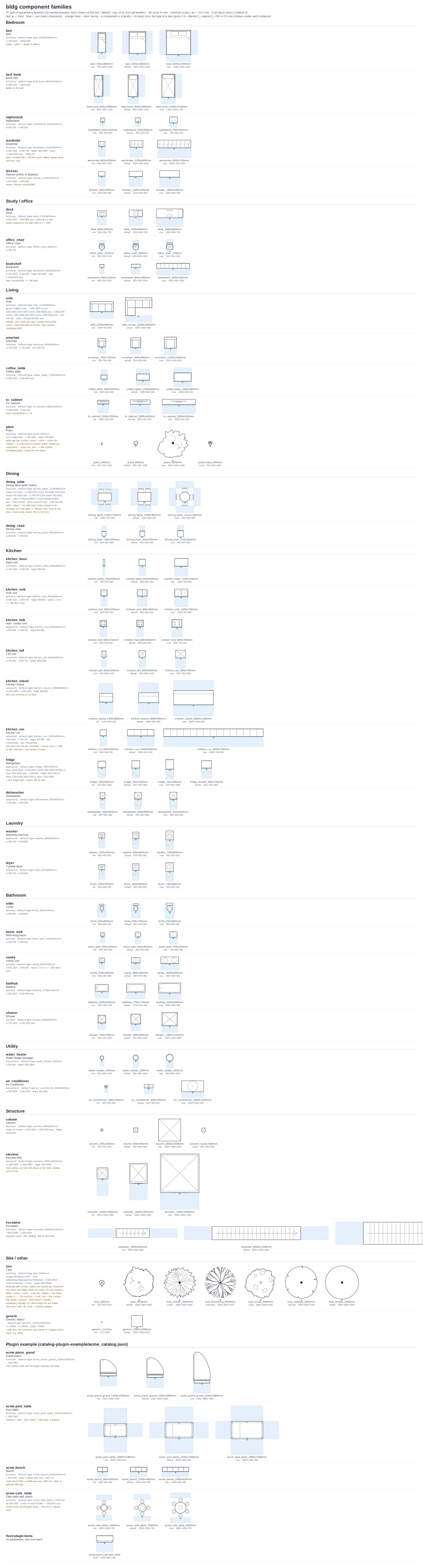
The furniture in the demo and the hero video was placed by a furnishing script (a greedy layout by room use: against walls, clear of door swings and of each other's use zones). It is a demo layout, not something read from the image; the pieces carry no evidence records, since evidence notes only the exceptions (a needs-check flag, a measured or traced value).
Drawing detail and scales
Detail levels and the print scale are export options, never data. The editor's Export menu:
| detail | doors | windows | components |
|---|---|---|---|
coarse (auto at 1:150 and smaller) | single-line leaf and arc, no frames | three lines | outline |
medium (auto at 1:75 to 1:149, and without a scale) | leaf rectangle (40 mm), frames at the jambs, thin solid arc | frames, mullions, one glass line per pane, sash arcs and arrows | outline + detail, dashed only for parts above the cut plane |
fine (auto above 1:75) | + casings and thresholds the document gives | + sash stiles, both glass faces | + appliance swings |
With a scale and a calibrated plan, SVG strokes are paper lineweights (wall cut 0.50 mm, leaves and frames 0.18, arcs and glass 0.13) and the SVG is sized in paper mm, so it prints to scale. The door and window geometry follows the opening type's parts (frame, leaves, threshold, layout mullions, all optional lengths in the document unit; missing ones take the typical set's defaults for the drawing, e.g. 1 3/8" leaves and 3/4" jambs in us_residential, and are reported as assumed); a pair's leaves are listed from the jamb the instance's hinge names. rough.w is the wall cut, frame included. The clear width and height derive from the parts (an instance's clear, else the type's, else the parts; unknown when a part they need is missing), never from the profile's defaults.
Door and window marks (M0921, D3068) are printed beside each opening by default (Layers ▾ Door / window marks hides them). The print scale sizes the drawing's text, dimensions, symbols, the north arrow and the grid bubbles; the editor's Export menu offers it (never the zoom). There is no DXF output (Known limitations).
Areas
floor_areas gives every plan's areas (gross floor area, room net areas, balconies / terraces apart: see Typical sets above). The gross floor area comes from the walls, not the room labels: every wall that encloses floor counts (an unlabelled space too), only free-standing walls that enclose nothing are left out. For China plans it adds the GB/T 50353-2013 building area estimate (建筑面积, storey_area / building_area, which refuse plans outside China): the storey outline to the outer faces of the exterior walls, half for a storey whose structural clear height (the soffit of the slab above less this one's top) is under 2.20 m (unknown on the top storey), balconies (semi balcony or loggia) inside the main structure full and outside half, an open one (a railing or virtual wall in its ring) half in its unit, terraces and other semi-outdoor or exterior spaces not counted, shafts filled and courtyards left open, and 套内建筑面积 for dwelling_unit groups (GB/T 17986.1). The SVG prints each room's net floor area under its name when the scale is known, and the editor's Areas tab lists the room areas, the gross floor area and (China) the building area estimate. The clause texts were recalled, not checked against an official copy; the area report marks them unverified. The compiler's own area_report() gives centerline (ring through the wall centrelines) and net areas.
Provenance and "needs re-measure"
evidence is a document-only, plan-wide side table: {ref, aspect (all|geometry|position|size|type|operation|text), method (measured|drawing|traced|read|inferred|assumed), source, needs_check, note} per element, type, level or source (traced = measured on a raster underlay, drawing = CAD / vector geometry; source names the metadata.sources entry). external_ids maps ids to other systems ({ref, source, external_id, role: element|void|fill|type}: an IFC door has a void and a fill). lint keeps it in step with its repairs and flags what it invents or moves by more than 20 mm as inferred, needs_check. The checks list the "needs re-measure" (待复尺) items, and the editor toggles the flag (⚑ / N) and filters on it.
bldg · Editor · Editor guide · Viewer · Format · Benchmarks · Limitations · Terms · Privacy · hello@usebldg.com